- Start trench layout from lowest point to highest point of area. The section containing the outlet will be your starting channel.
- Determine drainage channel run length.
- Determine type of slope necessary - continuous, stepped, or neutral.
- Continuous fall (slope) in one direction over 15 meters will require stepped fall.
- Step fall is achieved by using a series of neutral channel sections interspersed with sloped channel sections (i.e. 1000N, 1001, 1002, 1003, 1004, 1005, 1005N, 1006...1010, 1010N).
- Layout run(s) in sequential order from the lowest point to the highest point.
- Identify the starting upstream and ending downstream channel and assemble Starting End Cap(s) SC and Outlet End Cap(s) OC. The flow arrows, located under the channels, always point towards the Outlet End.
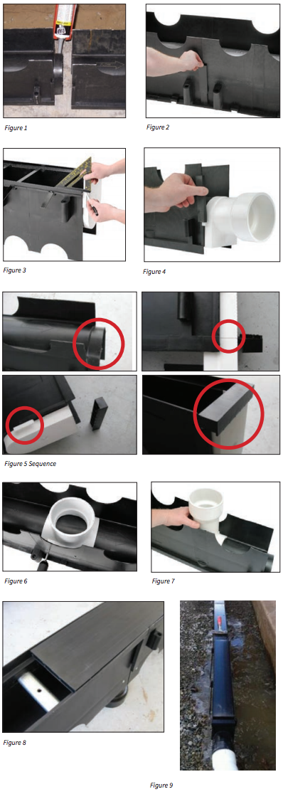
- Use the Quick Clips over the mounting brackets and apply appropriate sealant on tongue and recessed areas. (Figure 1 & 2).
- Starting End Cap(s) are fastened to the channels upstream end and Outlet End Cap(s) to the channels downstream end. To measure for end cap fit, slide end cap into tongue and recess portion of the channel it is being assembled to. Mark the end cap level with the grate ledge! (Not the top of the channel). FOR OVERLAY RAIL APPLICATIONS: Measure and cut to suit the extra depth of rail! Note: For Quick 12 series, measurements are made to the top of the frame and adjusted down 1/4” for the Finish Cap. Detailed instructions are available online at Quick-Trench.com or by request. (Figure 3 & 4).
- Bottom Outlets (BO) can be installed on any channel. Locate the lowest point on the pre-sloped channel and drill the appropriate sized hole for the chosen BO. We recommend using self-tapping screws for mounting along with a sealant. Once the outlet is positioned, screw through the channel skirt in to the boss area on the BO to secure during pour. Apply appropriate sealant around hole and saddle area of BO. (Figure 6 & 7).
- Place the pre-assembled length of the run into your trench. Ensure that all Grate Lock Downs, or frames for Quick 12 series, are in place before pouring concrete. Note: These cannot be installed later.
- Optionally for extra rigidity, you can install the Grate Locking devices and PVC Pour Boards before placing your Quick Trench Channel sections assembly in the prepared trench! Fig. 8 shows the installed Grate Locking device in place (before pour) and the optional 4.980” wide PVC Pour Board (reusable) which is oset to the Quick 6 channels joints.
- Now you are ready to pour